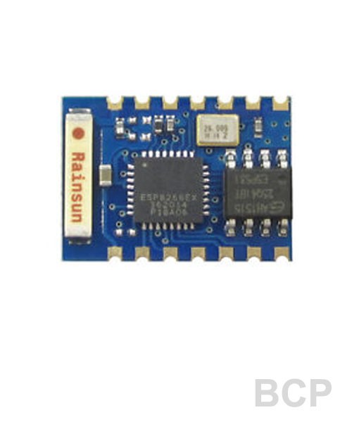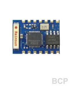
ESP-03 is a wifi module with own GPIO pins.
.
Specification
Pin configuration:
Pin
Name
Alternate Functions
Notes
1
GND
(Pin 1 is in the corner close to the xtal and away from antenna)
2
NC
3
UTXD
SPICS1, GPIO1, CLK_RTC
Typically used as serial uart0 TX
4
URXD
I2SO_DATA, GPIO3, CLK_XTAL
Typically used as serial uart0 RX
5
GPIO16
XPD_DCDC, RTC_GPIO0, EXT_WAKEUP, DEEPSLEEP
Connected to XPD_DCDC ESP pin, can also be connected to ESP EXT_RSTB (reset) pin by closing jumper near pin 8; Reset pin is active low and has an internal weak pull-up; Connecting jumper is required to wake-up ESP from deep-sleep: RTC produces pulse on XPD_DCDC pin that needs to be fed into EXT_RSTB pin
6
CH_PD
Power-down: low input powers down chip, high powers up; tie high for normal operation or module will not function
7
ANT
Wifi Antenna, do not connect
8
VCC
3.3V input (pin 8 is between antenna and ESP chip)
9
GPIO14
MTMS, I2SI_WS, SP_CLK
10
GPIO12
MTDI, I2SI_DATA, MISO
11
GPIO13
MTCK, I2SI_BCK, MOSI
12
GPIO15
MTDO, I2SO_BCK, SP_CS
At boot: must be low to enter flash or normal boot (high enters special boot modes)
13
GPIO2
I2SO_WS, U1TXD, U0TXD
At boot: must be high to enter flash or normal boot (low enters special boot modes); Typically is used as uart1 TX for debug logging
14
GPIO0
SPICS2, CLK_OUT
At boot: low causes bootloader to enter flash upload mode; high causes normal boot